Home |
Last modified: 18-05-2024 |
Pour environ 50€, il est possible d'assembler soi-même un appareil de mesure fiable de dioxide de carbone afin de vérifier la ventilation d'un lieu fermé et réduire ainsi le risque d'être contaminé par le virus respiratoire SARS-COV2.
Un appareil de base consiste en:
Outils :
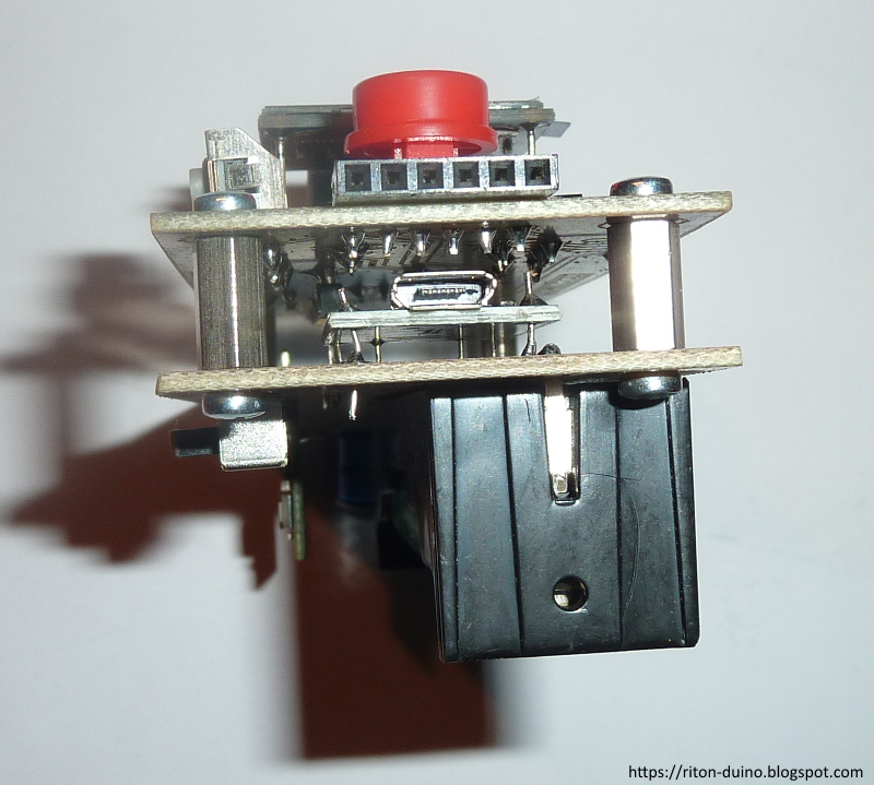
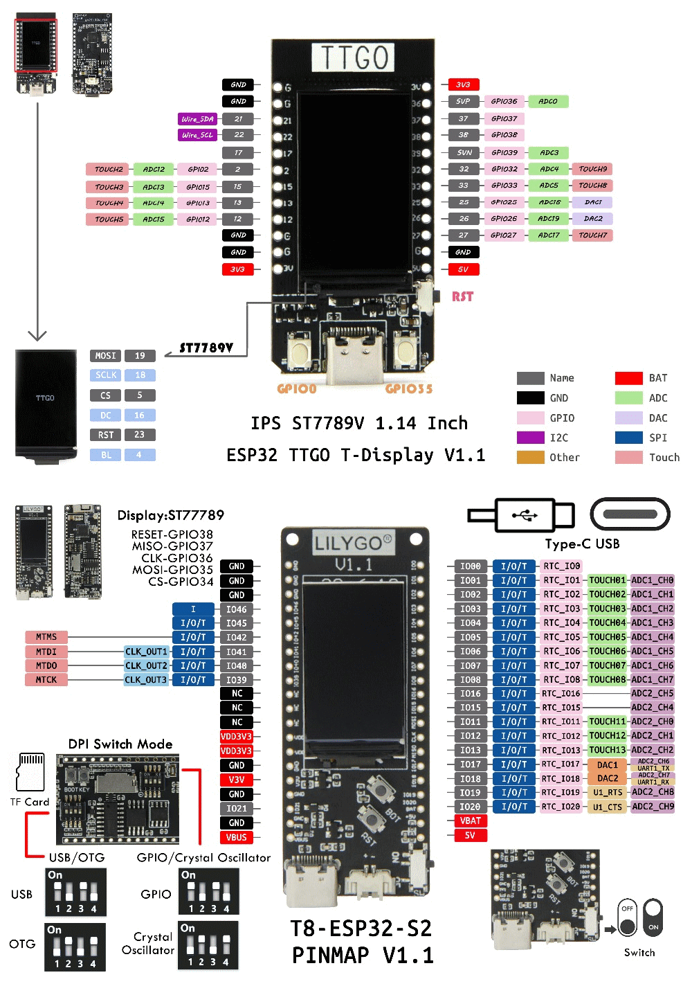
À l'expérience, la solution la plus simple, fiable et compacte consiste en 1) une sonde Sensirion (d'autant qu'elle fonctionne en 3,3V et économise donc de l'énergie, et permet également de mesurer la température et l'humidité) et 2) une carte TTGO T8 ESP32-S2 avec un écran intégré, un interrupteur et une prise JST qui permet d'y connecter un accumulateur afin de pouvoir l'utiliser sans accès à une prise murale et sans s'embêter avec une batterie externe USB.
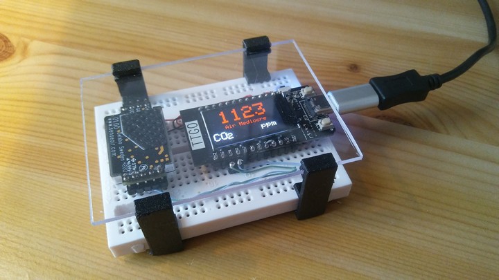
À l'aide d'un breadboard et des fils, on peut déjà tester le logiciel sans soudure.Si aucune expérience de la soudure, le mieux est de s'entraîner au préalable sur une simple carte type place de propotype PCB avant de se lancer pour de vrai. La soudure doit être appliquée rapidement et finement à la jonction entre la plaque et le fil.
Une sonde qui communique via UART utilise les pins TX+RX alors qu'elle utilise SDA+SCK si elle communique via I2C. Le Senseair S8 utilise le protocole Modbus via UART, TX sur le port du milieu et RX sur le port à côté
https://co2.rinolfi.ch : capteur Senseair S8 LP, carte microcontrôleur LILYGO TTGO T-Display ESP32 + code Arduino à compiler
Le code de GR a été modifié par NousAérons pour afficher le niveau de CO2 sous forme Nutriscore.
Belair : Carte TTGO T-DISPLAY ESP32 + capteur SENSEAIR S8
Grandair :
Composants:
Source : https://twitter.com/ArabellaBrayer
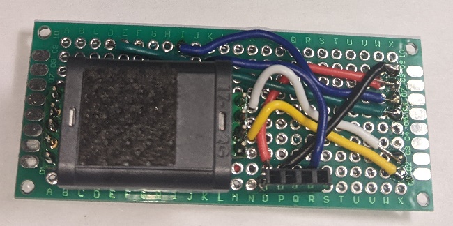
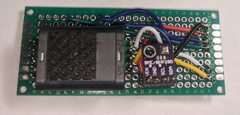
On peut fixer les éléments sur une plaquette en utilisant simplement de la colle cyanoacrylate (attention aux doigts + yeux) voire du scotch double-face, avant de souder les pattes nécessaires à la connexion.
Note : si l'IDE Arduino est très lent à fonctionner, essayer, le cas échéant, de désactiver l'antivirus, au moins le temps de faire le test. Autre solution à essayer : dans File > Preferences, décocher "Check for updates on start up".
Pour voir 1) où se trouve le fichier.bin compilé et 2) les commandes pour flasher la mémoire, et 3) partager le fichier binaire à des gens non équipés pour compiler :
Pour tester que le capteur est correctement calibré, il suffit de poser l'appareil en extérieur quelques minutes, et voir s'il descend bien à ~415PPM. Si le niveau ne se stabilise pas autour de cette valeur, un recalibrage est nécessaire.
La méthode ABC (Automatic Background Calibration) de recalibrage automatique de la sonde ne peut s'effectuer correctement qu'à condition qu'elle soit fréquemment exposée en fonctionnement à l'extérieur, qui est le niveau de référence… ce qui n'est pas le cas si l'appareil n'est utilisé qu'en intérieur et occasionnellement.
Dans ce cas, il faut effectuer régulièrement un recalibrage manuel : laisser l'appareil allumé en extérieur environ 30mn et appuyer sur le bouton à droite de la prise USB quand elle est vers le bas; cette méthode manuelle s'appelle "Background Calibration". La recalibration est correcte quand l'appareil affiche environ 415PPM (Source)
La carte T5 de Lilygo présente deux avantages : elle consomme très peu grâce à son écran de type "encre électronique" comme sur les liseuses, et elle possède un interrupteur pour allumer/éteindre la batterie connectée à la prise JST.
Important : commander la Lilygo TTGO T5 (AliExpress (2.3.1_2.13); Github) en version "DEPG0213BN 9102 Chip"; elle utilise une prise micro-USB. La version sans puce série utilise une prise USB-C et nécessite un connecteur USB T-U2T pour le flashage.
Outre le code source à compiler soi-même à l'aide de
l'outil ESP-IDF d'Espressif (Linux et Windows), ce
projet (Twitter, Github,
Discord)
propose aussi un binaire
prêt à l'emploi (il est également possible de flasher
avec un navigateur).
Si on peut commander un PCB à
un fabricant, cette
carte permet d'optimiser les connexions entre les éléments
via des pistes gravées et une prise à huit entrées entre
la carte, les sondes (CO2 et température) et la batterie… mais on peut
aussi utiliser un PCB classique voire même s'en passer complètement
en soudant les fils "en l'air", surtout si on simplifie en retirant
la sonde température du schéma.
Le fichier pour créer un boîtier à l'aide d'une imprimante 3D suppose l'utilisation d'un accumulateur de type FT103450P (1800mAh).
À la date d'octobre 2022 :
Branchement sonde Senseair S8 :
Brancher la carte sur un port USB puis chercher le nom du device avec "ls -al /dev/tty*" (ou via dmesg -wH voire tail -f /var/log/kern.log); ça peut être /dev/ttyACM0 . Pour la détection, la carte peut être sur ON ou OFF. Si elle n'apparaît pas, utiliser un autre câble USB, de préférence court et blindé.
Installer le ESP-IDF SDK (mène ici)
Compiler le code source sur Github :
Pour reprendre la compil après une session :
https://airmeter.io/make/esp32/firmware_build
you need python3.x and git
make sure both python and git are in your path
then
git clone --branch blah blah for espidf
cd esp-idf
setup.bat
then if setup is successful you run export.bat
and then cd into your airmeter folder
and do idf.py build
Afficher capacité batterie?
La carte (Github) est vendue sans ses "pin headers/connecteurs" soudées : il est possible de faire des tests sans les souder en 1) les déposants sur un bread board, 2) en appuyant la carte sur les headers pour faire contact, et 3) en utilisant des jumper cables pour relier les headers à la sonde.
À la date de juillet 2022…
#include <User_Setup.h>
avant de décommenter la ligne Setup71_*.hCode pour estimer capacité batterie ?
Alternatives : réécrire le code en Python pour CircuitPython; ou en C pour esp-idf .
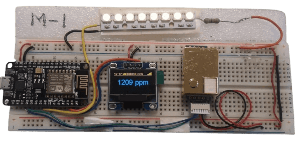
De par son écran OLED, cette combinaison consomme moins que l'écran TFT sur le TTGO; elle nécessite environ 170mA; une batterie externe de 2.700mAh permet donc de l'utiliser pendant environ 16 heures (et une batterie de 1.000mAh environ 4-5 heures). Le NodeMCU n'inclut pas de connecteur JST pour y relier une batterie.
TODO
? Font plus grande ? https://iotforgeeks.com/interface-i2c-oled-display-with-nodemcu/
? Désactiver wifi pour réduire consommation ? https://emariete.com/en/diy-co2-monitor-wifi/comment-page-11/#comment-2103
Liaisons :
Alimenter le NodeMCU et les composants à l'aide d'un accumulateur type 18650 nécessite des composants supplémentaires pour que le charge + décharge s'effectue sans risque.
Connecter un NodeMCU à un grand écran, une montre, un écran tactile, un écran basse conso :
https://www.co2.click/ecommerce/en/Model-Maker.html
M5Stack ESP32 Core Development Kit 1.54 inch eInk Screen, 390mAh 40€
+ PCB, USB-C power supply, @sensirion SCD-30 sensor
https://gitlab.com/co2.click/maker-edition/firmware
https://gitlab.com/co2.click/maker-edition/enclosure
DONE https://www.laboiteaformes.fr/capteur-co2/
: carte micro-contrôleur ESP8266 Wemos d1 mini, capteur CO2 SenseAir S8, écran
OLED SSD1306, LED RGB WS2812, boîtier imprimé 3D
https://www.laboiteaformes.fr/wp-content/uploads/2021/08/kit-co2.jpg
DONE http://nousaerons.fr/makersco2/#fabriquer
Assemblage un peu compliqué (écran séparé, capteur de température et d'humidité, LED, buzzer, encodeur rotatif)
Attention : ne pas brancher USB + batterie simultanément
https://le-17.net/dokuwiki/geek/co2/v3
Carte LOLIN D32 Pro V2.0.0 ESP32-WROVER
Code Arduino
Note : cet écran n'est plus commercialisé : voir si code mis à jour pour utiliser Tri-Color ePaper 2.13 (SSD1680)
Sonde Senseair S8 LP (004-0-0053) https://www.aliexpress.com/item/1005002774263066.html
Chargeur pour accu 16340 https://www.aliexpress.com/item/32955288000.html
http://www.wiki-rennes.fr/Capteur_CO2_Labfab
Détecteur de CO2 v3 (capteurs Senseair S8 LP et Sensirion SHT31D, carte LOLIN D32 PRO v2, écran LOLIN ePaper 2.13/Tri-Color ePaper 2.13, accumulateur type 16340, LEDs, buzzer, encodeur rotatif) https://le-17.net/dokuwiki/geek/co2/v3
https://www.reichelt.com/magazin/en/build-your-own-co2-measuring-device/ NodeMCU ESP32 + MH-Z19C
WeMos D1 Mini ESP8266 https://www.aliexpress.com/item/32643142716.html
NodeMcu V3 Lua WIFI development board based ESP8266 https://www.aliexpress.com/item/32654418046.html
How to reduce the ESP8266 power consumption?
https://gitlab.u-angers.fr/agodon/uaco2 : capteur SCD30, micro-contrôleur ESP32 NodeMCU, boîtier, LED RGB
MH-Z19
+ Domoticz + code MicroPython pour ESP32/ESP8266
MH-Z19 +
Domoticz + code Arduino compatible ESP32/ESP8266
https://www.instructables.com/CO2-Monitoring-As-an-Anti-Covid19-Measure/ Adafruit Feather M0 board, Gravity Analog Infrared CO2 Sensor For Arduino SEN0219, CR1220 battery, etc. ~100€
https://www.instructables.com/CO2-Display/ MZ-H19B sensor, Arduino Nano microcontroller, TM1637 display,
https://www.hackster.io/Seluxit/homemade-co2-sensor-unit-22a9d8 Raspberry Pi 3 B, SCD30, SparkFun Atmospheric Sensor Breakout - BME280
Breadboard + Senseair + Wemos D1 Mini https://fabmanager.latreso.fr/#!/projects/capteur-de-co2
Alternatives à une batterie externe USB:
"The ESP32 will want 5V or 3.3V ; with a single battery, a 3.3V LDO ("low-dropout regulator") could be used between the battery and the ESP32 to supply 3.3V or use a step up 5V regulator to supply 5V. A USB power bank is a set of LiPo batteries in a case with electronics to make 5V. With that battery, I'd use 2 in series, a USB power bank can be made."
Il faut utiliser l'UART (pins TX/RX, à croiser avec la carte) et le protocole Modbus
\Python\CircuitPython\senseairS8\
Technical Description — Modbus documentation Size Counts
https://www.seeedstudio.com/blog/2019/09/25/uart-vs-i2c-vs-spi-communication-protocols-and-uses/
https://github.com/SFeli/ESP32_S8
https://github.com/jcomas/S8_UART
https://www.wikidebrouillard.org/wiki/Item:Capteur_de_CO2_SENSEAIR_S8
https://projets.cohabit.fr/redmine/projects/projets-du-fablab/wiki/Senseair_S8
https://forum.nymea.io/t/connecting-to-co2-meter-senseair-s8-via-modbus/1046/3
https://co2.rinolfi.ch/stl/capteurCO2offline.ino
Source de Grégoire Rinolfi (via ESP32_S8)
https://circuitpython.org/board/lilygo_ttgo_t8_s2_st7789/
esptool.py --chip
esp32s2 --port COM9 --baud 115200 write_flash 0x000 myfile.bin
(si erreur,
vérifier la version d'esptool.py/exe, par exemple v4.4)
After flashing change the DIP switches (the ones closer to the USB-C connector) to OTG mode, when reconnected you should see the CIRCUITPY drive.
https://github.com/ndoornekamp/senseair_s8/
Module pour communiquer via le port série
"Une calibration « manuelle » du S8 est possible. Pour cela, il suffit de le placer dans un environnement où le taux de CO2 est entre 400 et 430 PPM, par exemple à « l’air libre », à l’extérieur, et de suivre la procédure suivante :
Made in Switzerland
"The Sensirion SCD-30 features an automatic calibration system, called by Sensirion Automatic Self-Calibration (ASC), and it works quite well."
SCD-40 https://www.adafruit.com/product/5187
SCD-41 https://www.adafruit.com/product/5190
"the unhoused SCD30 reacts very sensitive to airflow and provides incorrect readings if exposed to it" (Source)
https://developer.sensirion.com/archive/tutorials/create-your-own-co2-monitor/
Made in Sweden; self-calibration
S8-0053; "For applications where both power consumption and accuracy are critical factors" (Source)
https://www.aliexpress.com/item/4000884582128.html
https://www.amazon.fr/dp/B08QZ86NKD
Si nécessaire, il faut y souder des « pin headers ».
Consommation : average 18mA, peak 300mA
Note : Operation temperature: 0 to 50°C
MH-Z19B: Recommended, but watch out for fakes; Improved version of MH-Z19; Wait at least 2mn after powering up
MH-Z19C: Not recommended
MH-Z1311A: New kid on the block
CM1106SL-NS
Carte TTGO avec écran OLED et processeur ESP32
"On trouve parfois le microcontrôleur vendu déjà équipé de ces « pins headers », ce qui vous évitera une opération de soudure."
Consommation : ~80mA
"NodeMCU is a low-cost open source IoT platform. It initially included firmware which runs on the ESP8266 Wi-Fi SoC from Espressif Systems, and hardware which was based on the ESP-12 module. Later, support for the ESP32 32-bit MCU was added."
Kit de développement basé sur un ESP8266
Disponible avec un ESP8266 ou ESP32
Un écran OLED (SSD1306) est disponible (Lilygo TTGO)
Peut être alimenté par un chargeur USB
https://www.aliexpress.com/item/4000550036826.html
https://emariete.com/wp-content/uploads/2017/01/CameraZOOM-20170112203504828-1-1024x758.jpg
La carte WeMos D1 Mini utilise un ESP8266; version plus petit que le NodeMCU ESP8266; module Wifi intégré; capacité de mémoire et de calcul supérieure aux Arduino; microprocesseur Tensilica 32-bit RISC CPU Xtensa LX106; 64kB RAM, Flash 4000kB; Tension d’alimentation 7-12V
"The Arduino is nothing like a computer, as most of Arduino boards are not powerful enough to run an operating system. Indeed, Arduino is designed for electronics projects were you control I/O using C programming with the Arduino IDE installed in a Windows, Linux, or Mac computer. All the hard parts of setting up the hardware are however taken care of or abstracted, so Arduino boards are much easier to use than traditional MCU boards."
https://en.wikipedia.org/wiki/Raspberry_Pi
https://emariete.com/en/home-automation-at-home-raspberry-pi/
Modèles : 1, 2, 3, 4, 400, Zero, Pico
"Raspberry Pi boards run a fully-fledged Linux operating system [eg.Raspbian]".
https://en.wikipedia.org/wiki/BeagleBoard
Le plus simple est d'utiliser une petite boîte en plastique acrylique transparent, et de visser ou coller aux parois les composants avec du scotch double-face. Si nécessaire, percer des trous avec une perceuse afin l'air pénètre suffisamment jusqu'au capteur CO2.
Moins rigide : on peut aussi utiliser du polypropylène alvéolaire.
Plus sophistiqué : "imprimer" un boîtier avec une imprimante 3D.
Vérifier que l'outil supporte le micro-contrôleur qu'on souhaite utiliser.
Faut-il obligatoirement modifier les connecteurs DIP (pour accéder à la carte sous forme d'un disque externe ?) ?
Mu uniquement dispo pour Win64 : comment utiliser Notepad et Putty pour le port série ?
Comment installer une bibliothèque supplémentaire (pip install)
Le programme doit-il s'appeler code.py ?
REPL (Read-Evaluate-Print-Loop) interface accessible over serial; allows you to enter individual lines of code and have them run immediately.
Serial-USB converters just by different manufacturers. "An CP2102 considered as a better one but from my experience there is no difference. Some people complained about problem with CH340 driver installation. However mostly it's just an old OS issue."
https://riton-duino.blogspot.com/2020/02/les-convertisseurs-usb-serie.html
https://en.wikipedia.org/wiki/ESP_Easy: "free and open source MCU firmware for the Internet of things (IoT). and originally developed by the LetsControlIt.com community (formerly known as ESP8266.nu community). It runs on ESP8266 Wi-Fi based MCU (microcontroller unit) platforms for IoT from Espressif Systems. […] The firmware is built on the ESP8266 core for Arduino […]. In most cases, ESP8266 modules come with AT or NodeMCU LUA firmware, and you need to replace the existing firmware with the ESP Easy firmware by flashing the hardware with a flash tool to use it."
"Developed by Espressif, allows a very important energy saving, using the hardware for Wi-Fi that we already have in the ESP8266 and ESP32 chips. A process of sending data that with Wi-Fi can take about 10-12 seconds, with ESP-Now it is reduced to a few milliseconds. Of course, the routers and Wi-Fi access points that we have at home do not support ESP-Now, which makes it necessary to include a «translator» or «bridge», something than an ESP-Easy and Wifi. This gateway receives the data from the ultra-low consumption CO2 meter through ESP-Now and forwards it through wifi via MQTT (already available and working), HTTP or whatever we want." (link, link)
Alternative ouverte : LoRa(WAN)
Alternative IDE to the Arduino IDE.
https://dronebotworkshop.com/platformio/
"A variant of MicroPython. Most development is sponsored by Adafruit" (Source)
Why change the DIP switches? So the controller shows up as a disk drive called CIRCUITPY
Digital connections: As with the power supply connectors, you must be careful not to exceed their maximum current capabilities. The first two of these connections (0 and 1) are also labeled RX and TX, for receive and transmit. These connections are reserved for use in communication and are indirectly the receive and transmit connections for your USB link to your computer.
Whereas the flash memory is intended for storing program instructions (from sketches), the EEPROM is used to store data that you do not want to lose in the event of a reset or the power being turned off.
In Arduino programming the "boilerplate" code takes the form of the "setup" and "loop" functions that must always be present in a sketch.
The function pinMode sets a particular pin to be either an input or an output:
The Serial Monitor is part of the Arduino IDE. Its purpose is to act as a communication channel between your computer and the Arduino. You can type a message in the text entry area at the top of the Serial Monitor and when you press Return or click Send, it will send that message to the Arduino. Also if the Arduino has anything to say, this message will appear in the Serial Monitor. In both cases, the information is sent through the USB link.
There is a built-in function that you can use in your sketches to send a message back to the Serial Monitor. It is called Serial.println and it expects a single argument, which consists of the information that you want to send:
To read data from the serial port through the UART:
To prompt the user:
The most common use of digital inputs is to detect when a switch has been closed. A digital input can either be on or off. If the voltage at the input is less than 2.5V (halfway to 5V), it will be 0 (off), and if it is above 2.5V, it will be 1 (on).
A few of the digital pins—namely digital pins 3, 5, 6, 9, 10, and 11—can provide variable output other than just 5V or nothing. These are the pins on the board with a ~ or "PWM" next to them. PWM stands for Pulse Width Modulation, which refers to the means of controlling the amount of power at the output. It does so by rapidly turning the output on and off:
Digital inputs just give you an on/off answer as to what is happening at a particular pin on the Arduino board. Analog inputs, however, give you a value between 0 and 1023 depending on the voltage at the analog input pin.
The Arduino language is based on an earlier library in C called Wiring and it complements another library called Processing. The Processing library is very similar to Wiring, but it is based on the Java language rather than C and is used on your computer to link to your Arduino over USB. In fact, the Arduino IDE application that you run on your computer is based on Processing.
To store your data in flash memory, you have to include the PROGMEM library.
EEPROM is designed to remember its contents for many years. Despite its name, it is not really read-only. You can write to it. The official Arduino commands for reading and writing to EEPROM are just as awkward to use as the ones for using PROGMEM . You have to read and write to and from EEPROM one byte at a time. Fortunately, there is an alternative method that uses one of the libraries that Arduino itself uses called the AVR EEPROM library. This allows you to read and write as much data as will fit into your EEPROM with single commands.
The Arduino IDE comes with an LCD library. This greatly simplifies the process of using an LCD display. The library gives you useful functions that you can call:
OLED (organic light-emitting diode) displays are bright and crisp and are fast replacing LCD displays in consumer appliances. The type of OLED described here uses an interface bus called I2C (pronounced I squared C; serial bus standard commonly used to connect sensors and displays to microcontrollers like the Arduino. As well as the GND and positive power pins, it uses a data pin (SDA) and clock pin (SCK) to communicate with the microcontroller by sending serial data 1 bit at a time) and has a driver chip called the SD1306. Look for a device with just four interface pins as these are easiest to work with.
Before working with an I2C device, you need to find out the I2C address of the display. This will be a hexadecimal number and may be written on the back of the OLED display. Many low-cost eBay OLED displays use 0x3c. You will also need to install some libraries before the sketch will compile.
The ESP8266 is a WiFi System on a Chip. That is, it’s a single chip that pretty much does everything that an Arduino Uno equipped with a WiFi shield could do. It includes a few GPIO pins and an analog input and can be programmed from the Arduino IDE as if it were an official Arduino board. ESP-based boards require adding that board in the Arduino IDE (File > Prefences, followed by Tools > Boards), and a USB-Serial driver in the OS so the IDE can communicate with the board.
Some features of the Node MCU board:
Arduinos are simple microcontrollers. Most of the time, Arduino sketches are quite small, so using the C programming language works just fine. However, the programming language for Arduino is actually C++ rather than C.
For a full reference to all the Arduino commands, see the official Arduino documentation at www.arduino.cc/reference/en/
On Arduino board, the six pins labeled Analog In 0 to 5 can be used to measure the voltage connected to them (5V maximum) so the value can be used in a sketch. Although labeled as analog inputs, these connections can also be used as digital inputs or outputs. By default, however, they are analog inputs.
Pins labeled Digital 0 to 13 can be used as either inputs or outputs and are therefore called GPIOs (general purpose input outputs). When using them as outputs, you can control them from a sketch. If you turn them on from your sketch, they will be at 5V, and if you turn them off, they will be at 0V. As with the supply connectors, you have to be careful not to exceed their maximum current capabilities. These connections can supply 40 mA at 5V—more than enough power to light a standard LED, but not enough to drive an electric motor directly. Note that the total current used by all pins must not exceed 200mA.
The Arduino family of boards mostly use microcontrollers made by the company Microchip. They all have similar hardware design principles and, with the exception of the microcontrollers used in the Due and other ARM-based Arduinos such as the Zero, they have similar designs.
With applications like the AVRISPv2, AVRDragon, or the USBtinyISP, you can program the Arduino directly through such a programmer, bypassing the bootloader entirely. Bypassing the bootloader both reduces the amount of flash memory needed for the sketch and allows the Arduino to start more quickly, as the Bootloader spends a second or so checking to see if there is an incoming program each time the Arduino resets.
AVR Studio is the manufacturer’s proprietary software for programming the microcontrollers used in Arduinos. You can use it to program the Arduino itself, rather than using the Arduino IDE.
The NodeMCU and its relative, the Wemos D1 Mini, are extraordinarily low-cost Arduino-compatible boards with built-in WiFi connectivity. They are both based on the ESP8266 WiFi microcontroller module. It is possible to program these ESP8266-based devices with a range of programming languages including Arduino.
Often, the limited number of GPIO pins of the NodeMCU and other ESP8266-based Arduino-compatible boards is not a problem. However, sometimes you need more GPIO pins or might want to use Bluetooth. In which case, look for a board that uses the ESP32.
Interrupts allow microcontrollers to respond to events without having to poll continually to see if anything has changed. In addition to associating interrupts with certain pins you can also use timer-generated interrupts. Sometimes the idea of being able to interrupt what is going on in the loop function can seem like an easy way to catch keypresses and so on. But actually there are some fairly strict conditions regarding what you can reliably do within an Interrupt Service Routines (ISR.)
As well as interrupts being triggered by external events, you can also trigger ISRs to be called as a result of timed events. This capability can be really useful if you need to do something time-critical.
The Narcoleptic library is a great way of reducing the average power consumption of your ATmega-based Arduino. If you are using an Arduino-compatible board based on the ESP8266, then you can reduce the power consumption considerably by putting the board to sleep for a period of time.
Note that when the ESP8266 wakes from its sleep, it will not continue where it left off, but rather act as if it has been reset, running setup again. When awake, the NodeMCU used 80 mA; when put to sleep, it used around 10 mA. Other boards may do better, as most of this 10 mA must be the USB interface chip and other support components rather than the processor itself.
The ESP32 has many options when it comes to sleeping or specifically waking. You can set a periodic wakening using the same approach as for an ESP8266, but the device will also wake for various other stimuli, such as a digital input becoming high.
UART (Universal Asynchronous Receiver Transmitter), SPI, and TWI ("Two Wire Interface", a.k.a. I2C, pronounced "I squared C", a.k.a. Inter-Integrated Circuit) are three types of serial interfaces supported by some chips. Whereas digital and outputs are fine for connecting switches or LEDs with no intelligence, the serial interfaces to Arduino are often used to connect ICs or modules that might have their own microcontroller built-in. Serial communication is the norm when you need to send and receive more information than a single high or low. This includes some sensor chips that might send their readings as a stream of binary digits, or display modules that expect to be sent a stream of binary digits telling them what to display.
While you will occasionally find parallel interfaces used for communicating between microcontrollers and modules, these suffer from the disadvantage that they require one GPIO line for each bit being transferred. It is therefore much more common to use a serial interface where one GPIO pin is used to send or receive data one bit at a time. This is slower than a parallel interface but has the advantage that it uses less GPIO pins.
The I2C standard is defined as a "bus" standard because its use is not limited to connecting one component directly to another. Say you have a display connected to a microcontroller; using the same two bus pins, you can connect a whole set of "slave" devices to a "master" device. The Arduino acts as the "master," and each of the "slaves" has a unique address that identifies the device on the bus.
I2C uses two wires to transmit and receive data (hence, the alternative name of Two Wire Interface). These two lines are called the Serial Clock Line (SCL) and the Serial Data Line (SDA).
The Arduino software includes a library called Wire that handles all the timing complexity, so we can just send and receive bytes of data. The Wire library will buffer incoming I2C data.
The 1-Wire standard created by Dallas Semiconductor has taken this to its logical extreme by reducing the data lines used to just one. The bus is slower than I2C, and it has the interesting feature of parasitic power, which allows remote devices to be connected to a microcontroller with just two wires, GND (ground), and combined power and data wire. Just as with I2C, 1-Wire uses the master and slave concept for devices. The microcontroller is the master and the peripherals are the slaves. Each slave device is given a unique ID known as its "address" during manufacturing, so it can be identified on the bus when there are multiple slaves.
The Serial Peripheral Interface (SPI) bus is yet another serial bus standard that you can use to connect peripherals to your Arduino. It is fast but uses four pins compared with the two that I2C uses. SPI is not actually a true bus, as the fourth pin is a Save Select (SS) pin. One Arduino pin must be used for SS for each peripheral on the bus. This setup effectively addresses the right peripheral on the bus by turning all the other peripherals off. A wide range of SPI devices are available, including many of the same type of devices available for I2C. It is not uncommon for peripherals to have both I2C and SPI interfaces.
You use the serial interface when you program your Arduino board, and you also use it to communicate with the Serial Monitor to send data back and forth to the Arduino from your computer. As well as communicating via the USB interface, you can also communicate directly to the serial interface. The direct interface that skips the USB connection is often referred to as TTL Serial, or just Serial. TTL is a reference to Transistor-Transistor Logic, a now redundant technology that used 5V logic levels. Serial communication, of this kind, is not a bus. It is point-to-point communication. Only two devices are involved—generally an Arduino and a peripheral. Peripherals that use TTL Serial rather than I2C or SPI tend to be larger devices or devices that have been around for a long time and traditionally always had a TTL Serial interface. This also includes devices originally intended to be connected to the serial port of a PC. Examples include GPS modules, multimeters with data logging features, and barcode and RFID readers.
Note : On some controllers, the Rx and Tx pins (Receive and Transmit, respectively) also double as pins D0 and D1; If you use them as general I/O pins, you will probably find that you cannot program your Arduino while they are attached to external electronics. Arduino compatible boards such as those based on the ESP32 or ESP8266 generally have dedicated serial pins labeled TX and RX.
Adafruit and SparkFun both produce great ranges of Arduino-compatible boards. When it comes to low-cost ESP8266 and ESP32 boards, then eBay and Amazon are the places to go, although if they are coming from China you may have to wait a few weeks.